With the machineless method of cooling cargo in the cargo spaces of refrigerated trucks, solid carbon dioxide (dry ice), frozen eutectic solutions (sodium or potassium chloride, etc.) and liquefied gases (liquid carbon dioxide, liquid nitrogen) are used.
Sublimation of dry ice (transition from a solid to a gaseous state) allows you to achieve low temperatures inside the van (body). The high density (1500 kg/m 3 ) of dry ice makes it possible to create compact refrigerated units. Dry ice is placed in bunkers located under the ceiling of the cargo area. The bunker is loaded through a special hatch without violating the tightness of the chamber.
Eutectic solutions (sodium chloride, potassium chloride, aqueous solution of ethylene glycol, etc.) are placed in containers (zerotors) and frozen in stationary refrigeration units or in another way. When thawing eutectic solutions due to the absorption of heat by them, the temperature in the body can be maintained from minus 2 to minus 9 ° C for 12 … 15 hours.
The use of zerotors and bunkers ensures only the maintenance of the temperature range (interval) at a certain level and does not allow to regulate the temperature in the cargo area of the van. A more advanced cooling system is a system using liquid carbon dioxide. The required temperature is maintained by controlling the valve for regulating the supply of carbon dioxide to the cargo space. The disadvantage of this cooling is the specific effect of carbon dioxide on many products. In addition, the cost of carbon dioxide is relatively high compared to other refrigerants. Therefore, liquid nitrogen is increasingly used as a refrigerant in refrigerators.
The nitrogen cooling system (Fig. 20) works as follows. A temperature sensor 11 is installed in the cargo room of the refrigerator, which transmits a signal to relay 8, which is set to a certain temperature. At the command of the temperature relay 8, the solenoid valve 9 for supplying liquid nitrogen opens or closes. Liquid nitrogen from the pressure vessel 2 enters the distribution (spray) manifold 10. As a result of heat exchange with the environment in the cargo space, nitrogen is evaporated and the environment is cooled (lowered in temperature). After the medium has cooled to the set temperature, the temperature switch 8 gives a signal to close the valve 9. The cooling system is blocked with the operation of the van doors, and in such a way that the system is turned off when the doors are open. This is due not only to security requirements,
An excess pressure of about 100 kPa is maintained inside the vessel 2. When the standard pressure is exceeded, vaporous nitrogen is discharged through the safety valve 12. Excess nitrogen in the body of the van also exits through a special exhaust valve, usually located in the van door. With the help of nitrogen cooling it is possible to provide very low temperatures in the cargo compartment, however, they are usually maintained in the range from positive temperatures to minus 20 … 30 ° C. The time to reach the temperature regime, for example, to a temperature of minus 20 ° C, for large refrigerators is only 10 … 15 minutes, while with a machine cooling method it is 5 … 6 hours.
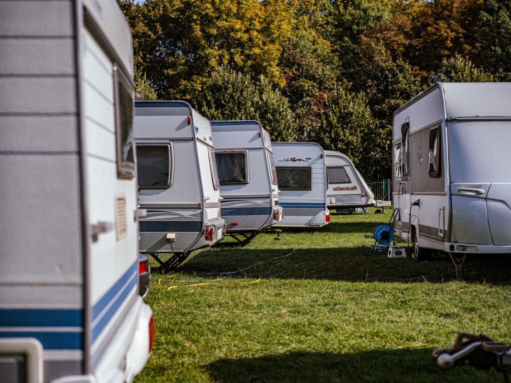
General arrangement of a refrigerated truck equipped with a refrigeration unit
A refrigerated truck is a van or van train (trailer, semi-trailer) equipped with an isothermal body and a refrigeration unit (Fig. 23).
Most refrigeration units of refrigerated trucks provide cooling and heating, which is why they are also called refrigeration and heating units. Refrigeration units provide maintenance of temperature conditions from minus 25°C to plus 12°C in isothermal bodies of vans, trailers and semi-trailers with a volume of 2 to 120 m 3 .
The refrigeration unit of small and medium-sized refrigerated trucks can have two compressors (Fig. 24): a road (main) compressor driven by a car engine (directly through a V-belt drive or from a car generator) and a parking (additional) compressor driven by an electric motor and powered by external power supply.
The liquid refrigerant through the check valve 22, the valve 24 enters the receiver 2, then through the valve 3, the liquid refrigerant indicator 4, the filter drier 5 to absorb the moisture present in the refrigerant, the heat exchanger 12 to the thermostatic valve 10. With the help of the latter, the degree of filling of the refrigeration refrigerant installations depending on the temperature of its vapors. Automatic regulation of the system is provided by means of a bulb 11 fixed on the outlet pipeline of the evaporator 8 and an equalizing line connected near the bulb.
The refrigerant pressure at the outlet of the thermostatic valve decreases to the evaporation pressure, and the refrigerant enters the evaporator 8 through distributor 6. Distributor 6 ensures uniform distribution of the refrigerant over all sections of the evaporator, through the separating tubes of which heat is supplied from the cooled medium, which ensures the transition of the refrigerant into a gaseous state . The refrigerant vapor through the heat exchanger 12, shock-absorbing insert 13 and valve 14 are again returned to the compressor.
To heat the body, the two-way valve 18 is moved to the position corresponding to the flow of hot refrigerant vapor not into the condenser, but directly into the evaporator 8 through the vapor distributor 9. The refrigerant vapor is again sucked in by the compressor from the evaporator through the heat exchanger 12, damping insert 13 and valve 14. To increase efficiency operation of the condenser and evaporator, fans 21 and 7 are used.
The removal of the “snow coat” from the evaporator occurs in the “defrosting” mode. This mode differs from the “heating” mode only by turning off the operation of the evaporator fan 7. The pressure in the suction line is controlled by pressure gauge 16. The maximum pressure in the system is limited by an automatic protection device 23, which stops the unit when the pressure rises above 1.6 MPa, and turns it on again when the pressure drops to an acceptable value.
The two-way valve is controlled by solenoid valve 19. In the “cooling” mode, no current is supplied to the solenoid valve, and the compressor discharge pipe is permanently connected to the condenser. To facilitate the acceleration of the compressor at the time of start-up, a solenoid valve connects the suction and discharge pipelines. In the “heating” and “defrosting” modes, current is constantly supplied to the solenoid valve, as a result of which the two-way valve ensures the supply of refrigerant to the evaporator.
Thermal insulation for vans
Isothermal vans, refrigerated vans and heated vans are equipped with thermal insulation, which is located between the outer and inner linings. The body of the van is made in a frame or frameless design
Frame vans are used on refrigerators designed to transport goods suspended from hooks on the roof (for example, meat carcasses). The riveted frames of modern vans are made of aluminum or steel profiles. The fastening elements of the inner and outer panels to the frame are located on the side of the frame and are covered with outer or inner lining. In this design, “thermal bridges” are eliminated – the junction of the metal frame with the cladding.