In the realm of RV electrical setups, the choice of wiring configuration takes center stage. Ensuring the inverter’s role does not overlap with that of the converter-charger is paramount. Professional installation is strongly recommended, a piece of advice not to be taken lightly.
With the acquisition of a spanking new RV inverter, the task at hand revolves around its integration. Below lies an elucidation of the procedure to seamlessly link the inverter with the RV’s electrical system. For a more visual guide, accompanying diagrams are provided.
Inverter Wiring Process
The inverter, a gadget designed to transform Direct Current (DC) to Alternating Current (AC), presents an intriguing subject. This discussion takes the form of a straightforward illustration where an inverter interfaces with a battery bank.
For those seeking more comprehensive insights, a PDF version is readily available. The illustrated configuration showcases the parallel connection of three batteries, collectively empowering the inverter’s DC terminals. Notably, a fuse box finds its place within the positive (red) wire. Amplifying the battery bank’s capacity by integrating more batteries results in an extended power availability. Following this, the inverter takes the reins, converting power to AC, subsequently tapped from its AC output socket.
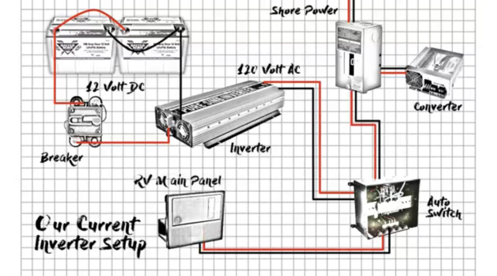
Navigating the 2-Way Changeover (Inverter or AC Shore Line Supply to RV)
- A 2-Way changeover mechanism takes the spotlight, orchestrating the transition of output power between two sources—namely, the inverter and the AC shore power line. This manually operated circuit, depicted below, is obtainable at a budget-friendly price point;
- The flow of power from the AC shoreline courses through a circuit breaker. On one input terminal of the 2-way changeover switch, the live and neutral wires from the inverter find their connection, while the AC shore power line occupies the alternate input terminal;
- Emanating from the output terminals of the 2-way changeover switch is the AC load of the RV. Safeguarding the system, the ground wire seeks its anchorage to the ground terminal or the body of the 2-way switch.
Exploring the 3-Way Changeover (Inverter, AC Shore Line, AC Generator to RV)
A 3-Way changeover setup commands attention as it orchestrates output redirection among three inputs: the AC shoreline, the AC generator, and the inverter. Through toggle control, the output terminal establishes a connection with any of these inputs, subsequently supplying the RV’s AC load.
Both the AC shoreline and AC generator contributions are channelled via dedicated circuit breakers, ensuring a streamlined and protected flow of power. The 3-way changeover switch, visually represented below, assumes the manual operation mode, reflecting its user-friendly nature. Additionally, a detailed reference to the specific switch model adds a touch of precision to the diagram, underscoring the significance of making informed choices in constructing a robust and versatile power management system for an RV.
Energizing Battery Charge via AC Shore Line, AC Generator, and Solar Power
The vitality of the RV’s battery bank fuels the appliances within. Charging these essential batteries involves a comprehensive schematic and wiring representation.
Incorporating a 2-way changeover switch comes into play, enabling the selection of power origin either from the AC shoreline or the AC generator. These inputs correspond to the first and second slots of the changeover switch, respectively.
Steering the charge towards the batteries, a converter emerges. Operating as a bridge between Alternating Current (AC) and Direct Current (DC), the converter’s connection to the batteries is crucial. A safeguard in the form of a fuse graces the positive (red) wire.
Unveiling the Trio: AC Shore Line, AC Generator, and Solar Charging
A broader horizon for battery charging emerges, this time integrating the prowess of solar energy. Elaborate diagrams and schematics guide the way.
The output of the solar panel makes its initial halt at the solar charge controller. Branching off from the controller, an option to link with the RV’s DC load materializes. The solar charge controller’s journey concludes with a fuse box engagement on the positive (red) wire.
This array of diagrams showcases a trinity of charging avenues for the battery bank. The trio consists of the AC shoreline, the AC generator, and the solar energy system, each possessing the capacity to rejuvenate the battery bank. Should a visual accompaniment be desired, both a PDF schematic and a wiring diagram can be accessed for each setup.
RV Wiring: A Comprehensive Overview
The discussion now shifts towards a holistic exploration of RV wiring, interconnecting the previously elucidated circuits. This section unites all these components into a coherent setup.
In this synthesis, the battery bank garners charge from both the solar system and the converter’s output. The converter, versatile in its power sources, can draw energy from either the AC shoreline or the AC generator. A 2-way changeover switch facilitates the seamless transition between these sources.
On the AC output front, the introduction of a 3-way switch introduces a trio of input options:
- Directly from the AC shoreline;
- Sourced from the AC generator;
- Via the AC output of the inverter, itself fed by the battery bank.
The output stemming from this 3-way changeover switch interconnects with the RV’s AC load. Simultaneously, the DC load of the RV forges a connection with the solar charge controller. It is imperative that all appliances within the RV are tethered both parallel to each other and to the source of Alternating Current (AC). For a comprehensive visual reference, the complete RV wiring layout can be accessed in a single PDF file encompassing both schematics and wiring details.
Guidelines for Inverter Selection in an RV Setting
Within the realm of Recreational Vehicles (RVs), which often double as living spaces, a 12-volt battery configuration or a 12VDC solar setup is commonly employed. The integration of an inverter steps in to transform this 12-volt power source, hailing from batteries or solar panels, into the 110 VAC standard in the USA (or 220 VAC in some regions). This transition empowers the usage of home appliances, functioning on AC power, within the RV premises.
Three distinct types of inverters emerge, categorized by the output waveform they generate:
1. Pure Sine Wave Inverters
The output of these inverters mirrors a clean sine wave, closely resembling the power delivered by utility companies or standby generators. This clean AC power sustains devices without inflicting damage. While these inverters offer top-notch quality, they are also the priciest among the options under consideration.
2. Modified Sine Wave Inverters
These inverters produce a waveform with noticeable corners and edges, deviating from the smooth lines of a pure sine wave. While they are more economical, they fall short of providing pristine power to devices. This category might introduce some noise during device operation, potentially affecting sensitive electronics or causing audible disturbances. It’s important to weigh the cost-effectiveness of modified sine wave inverters against the specific requirements of the devices they will power.
While these inverters might be a suitable choice for devices that are less sensitive to power quality, such as basic lighting or certain types of motors, caution should be exercised when considering their use for more delicate electronics. Complex equipment like computers, audio systems, or medical devices might experience issues when subjected to the irregular waveform of a modified sine wave inverter. Therefore, the decision to opt for a modified sine wave inverter should be based on a clear understanding of the devices to be powered and their compatibility with this type of power output.
3. Square Wave Inverters
The waveform of square wave inverters, as displayed by an oscilloscope, takes on an even more distinct shape. This type of inverter exhibits an abrupt transition from maximum to minimum values. These inverters are the most budget-friendly but carry the potential to harm devices. When operated, devices on square wave inverters tend to produce more pronounced noise.
The selection process involves aligning the inverter type with one’s budget and the intended devices. The power output of the inverter is another crucial factor. To determine this, the cumulative power consumption of the devices earmarked for inverter operation needs to be evaluated. For instance, considering a TV, electric kettle, and microwave oven, the individual power ratings of each device are summed up to establish the required inverter power.
After totaling the power in watts, one can seek an inverter in the market with a power rating that surpasses this calculation. For example, if the calculated power requirement is 2300 watts, selecting a 3000-watt pure sine wave inverter from any reputable manufacturer could be an apt choice for the RV setup.
Conclusion
In the intricate world of RV electrical systems, the quest for optimal power distribution and management is a journey worth undertaking. This exploration has unveiled a multifaceted tapestry of circuits, switches, and inverters that harmoniously orchestrate the flow of energy within an RV.
- From the initial discussions on inverter wiring, where the careful integration of components ensures uninterrupted power conversion, to the intricate dance of changeover switches that seamlessly alternate between sources, each step plays a crucial role in maintaining a well-functioning electrical system;
- The three-tiered approach to inverter selection – pure sine wave, modified sine wave, and square wave – underscores the importance of matching the power output to the intended usage and budget constraints. This not only guarantees the right quality of power for the devices but also safeguards them from potential damage. This careful selection process ensures a harmonious coexistence of appliances and the power supply, creating a comfortable and functional environment within the RV;
- As the final pieces of the puzzle come together, the intricate network of circuits converges to empower RV enthusiasts with the ability to harness various power sources, enabling them to seamlessly transition from the tranquility of solar energy to the reliability of shore power or generator-supplied electricity. This amalgamation of diverse power sources, changeover mechanisms, and inverters empowers RV dwellers with the conveniences of modern living while on the road.
In conclusion, the intricate dance of circuits, switches, and inverters within the realm of RV electrical systems presents both a challenge and an opportunity. By embracing the intricacies of wiring and power source selection, RV owners can create a dynamic and functional space that seamlessly merges mobility with modernity. The quest for optimized energy management in RVs is not just a technical endeavor; it’s a pathway to transforming a vehicle into a home on wheels, where comfort and convenience know no bounds.